Another method, that is more appropriate for applications, is to monitor
activity at a point in the medium, as if by a recording electrode. In this
case both the position of the recording electrode and the time delay ![]() between recording wave arrival and stimulation are all arbitrary, but in
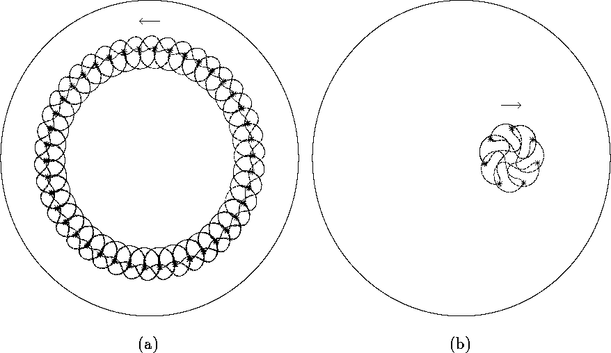
fact turn out to be of great importance. Figure 4 illustrates the
synchronization of the rotations of the core of the spiral by the resonant
forcing, when the wavetip drifts around a stable limit cycle, a circle with
a centre that coincides with the location of the recording electrode point;
in (a) the symmetry center is the centre of the medium, in (b) the symmetry
centre is shifted at the point with the radius
between recording wave arrival and stimulation are all arbitrary, but in
fact turn out to be of great importance. Figure 4 illustrates the
synchronization of the rotations of the core of the spiral by the resonant
forcing, when the wavetip drifts around a stable limit cycle, a circle with
a centre that coincides with the location of the recording electrode point;
in (a) the symmetry center is the centre of the medium, in (b) the symmetry
centre is shifted at the point with the radius ![]() . An
increase of amplitude A results in an increase of the angular velocity of
the drift along these circles, but does not influence their radii. Changing
the time delay, one can change the radius and/or reverse the direction of
the drift along the circle, in (a) the drift occurs in the counter-clockwise
direction while in (b) in the opposite direction. All this is consistent
with the phenomenological theory of the resonant drift described in [7]. Indeed, the equations (63) therein, that describe the
feedback-driven resonance drift in the absence of interactions with the
boundary, can be rewritten in the form
. An
increase of amplitude A results in an increase of the angular velocity of
the drift along these circles, but does not influence their radii. Changing
the time delay, one can change the radius and/or reverse the direction of
the drift along the circle, in (a) the drift occurs in the counter-clockwise
direction while in (b) in the opposite direction. All this is consistent
with the phenomenological theory of the resonant drift described in [7]. Indeed, the equations (63) therein, that describe the
feedback-driven resonance drift in the absence of interactions with the
boundary, can be rewritten in the form
where ![]() are polar coordinates of the spiral wave core,
are polar coordinates of the spiral wave core, ![]() corresponds to the recording electrode;
corresponds to the recording electrode; ![]() ,
, ![]() and T are the asymptotic wavelength and the period of
the wave respectively, and
and T are the asymptotic wavelength and the period of
the wave respectively, and ![]() is the stimulation delay; c is a
constant determined by the forcing amplitude A. Equations (10)
admit a discrete family of limit cycles
is the stimulation delay; c is a
constant determined by the forcing amplitude A. Equations (10)
admit a discrete family of limit cycles
Thus the feedback results in a synchronization of the tip motion by the external stimuli so that, after some transient process, the wavetip approaches a closed circular trajectory centered at the measuring point. This leads to an idea of extinguishing the resonantly drifting spiral wave near the boundary by resonant drift along a circular arc which would intersect the boundary. To do this one could set the recording electrode at the boundary as proposed in [7].

Figure 4: Tip trajectories computed under feedback control by a recording
electrode sited at the centre, ![]() = 0, of the
medium in (a) and at
= 0, of the
medium in (a) and at ![]() = 10 in (b). Amplitude of
stimulation A=3. In both (a) and (b) the spiral waves are rotating
counter-clockwise.
= 10 in (b). Amplitude of
stimulation A=3. In both (a) and (b) the spiral waves are rotating
counter-clockwise.
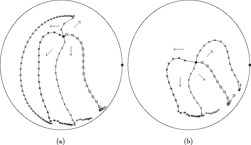
Figure 5 illustrates the process of extinguishing the spiral waves in the case when the recording electrode is set at the boundary. Most of the core trajectories do not resemble circular arcs because the core reaches the boundary during the transient processes. Notice that the shape of these trajectories before touching the boundary is similar to those obtained in square media, see Figure 14 in [7].

Figure 5: Resonant drift under feedback control by a recording electrode, the
perturbation of amplitude A=3 is applied at fixed time after
the wavefront reaches the recording site. The four wave's core
trajectories correspond to different initial wave's phases, 0,
![]() ,
, ![]() , and
, and ![]() , at which the first
perturbation pulse was applied. Shown are positions of the tip at the
times the perturbations were applied. The solid circle marks the
recording site.
, at which the first
perturbation pulse was applied. Shown are positions of the tip at the
times the perturbations were applied. The solid circle marks the
recording site.
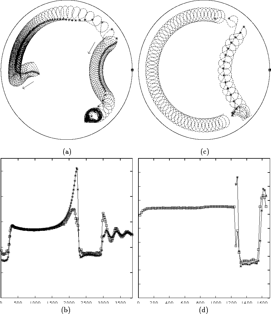
We have seen that drift along a circular trajectory can occur in the absence of interaction with boundaries due to the symmetry of drift motion equations. However, similar drift can occur even in case of strong interaction with boundary. In Fig. 6(a), the resonantly drifting spiral wave is first pushed to and then moves along a circular trajectory clockwise around the boundary, increasing in drift velocity as it approaches the recording site. When the spiral tip comes close to the recording site, the tip is detached from the boundary and moves along a smaller circular trajectory inside the medium, this time counter-clockwise, then attaches to the boundary and follows the boundary in a circular clockwise motion and finally freezes. These nearly circular motions along the boundary result from the small difference between the perturbation frequency and the spiral wavetip frequency seen in Figures 6(b), which in turn is related to the fact that in the absence of forcing, the drift due to interaction with boundary is also circular, as shown in Fig. 1(b). This interpretation is confirmed by the next numerical experiment shown in Fig. 6(c),(d), which stimulated a similarly complicated shape of trajectory by varying the stimulation protocol. First, the spiral wave was set to drift clockwise along the boundary without external forcing (left half of medium in Fig. 6(c)). Then a feedback-driven forcing was started (shown by asterisks), which led to detaching the spiral wave from the boundary and to its drift counterclockwise through the interior of the medium, until reaching the boundary again, which ended this time up with extinguishing the spiral wave.

Figure 6: A complicated sequence of spiral wave
boundary interactions, with
resonant drift under feedback control by a recording electrode,
repetitive stimulation with uniform amplitude A=2.5 in (a),(b) and
A=3 in (c),(d). The * marks the positions of the spiral's wavetip at
the time moments when the perturbation is applied; the solid circle
marks the recording site. (a) Tip trajectory of the resonantly drifting
wave, which is first driven towards the boundary, moves
circumferentially around the boundary, gradually speeding up, until it
is repelled from the boundary and undergoes a Larmor-type drift before
returning to the boundary and finally being frozen at the boundary. (b)
Dependence of the instantaneous frequency of the spiral's wavetip
(marked by the squares) and the frequency of stimulation (marked by the
*) on time. (c) Shown is the tip trajectory of a spiral wave drifting
clockwise along the boundary in the absence of any external forcing,
the left part of the figure; when external forcing is turned on, the
trajectory executes a nearly circular motion around the recording
electrode site, the right part of the figure. (d) Dependence of the
instantaneous frequency of the rotation of the spiral's wavetip motion
of 6(c) (marked by the squares) and the frequency of stimulation
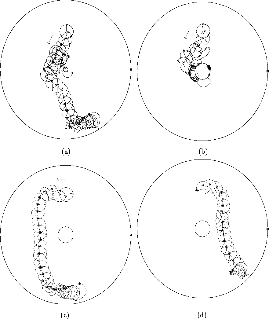
(marked by the *) on time. Figure 7 illustrates interactions between resonant drift under feedback
control and an inexcitable hole; in (a) the tip trajectory is trapped by the
small hole, and breaks free, to be extinguished at the boundary; in (b) the
spiral wave is trapped and is bound to the larger hole, while in (c) and (d)
the tip trajectory bypasses the hole and the spiral wave is extinguished.
This confirms the importance of the time delay parameter in the feedback
controlled resonant drift. An appropriately chosen time delay parameter
allows the resonantly drifting spiral waves to bypass the obstacle and reach
the boundary where it is finally extinguished.

Figure 7: Resonant drift under feedback control by a recording electrode in
circular media with circular obstacles and perturbations of
amplitude A=3. The * marks the position of the spiral's wavetip at
the time when the perturbation is applied; the solid circle marks the
recording site. (a) Hole with radius ![]() being less then the wave's
core size. (b)-(d) Hole with radius
being less then the wave's
core size. (b)-(d) Hole with radius ![]() of the same order as the
core of the unperturbed spiral. Initial wave's phases at which the
first stimulation was applied are 0 in (c),
of the same order as the
core of the unperturbed spiral. Initial wave's phases at which the
first stimulation was applied are 0 in (c), ![]() in (b),
and
in (b),
and ![]() in (d).
in (d).