Figure 8: A
The tip of the spiral wave solutions presented in Fig. 3-7 moves irregularly in a complicated trajectory, but does not move out of the medium: if the medium is large enough to contain the early transient motion around an almost linear core then the spiral wave remains in the medium.
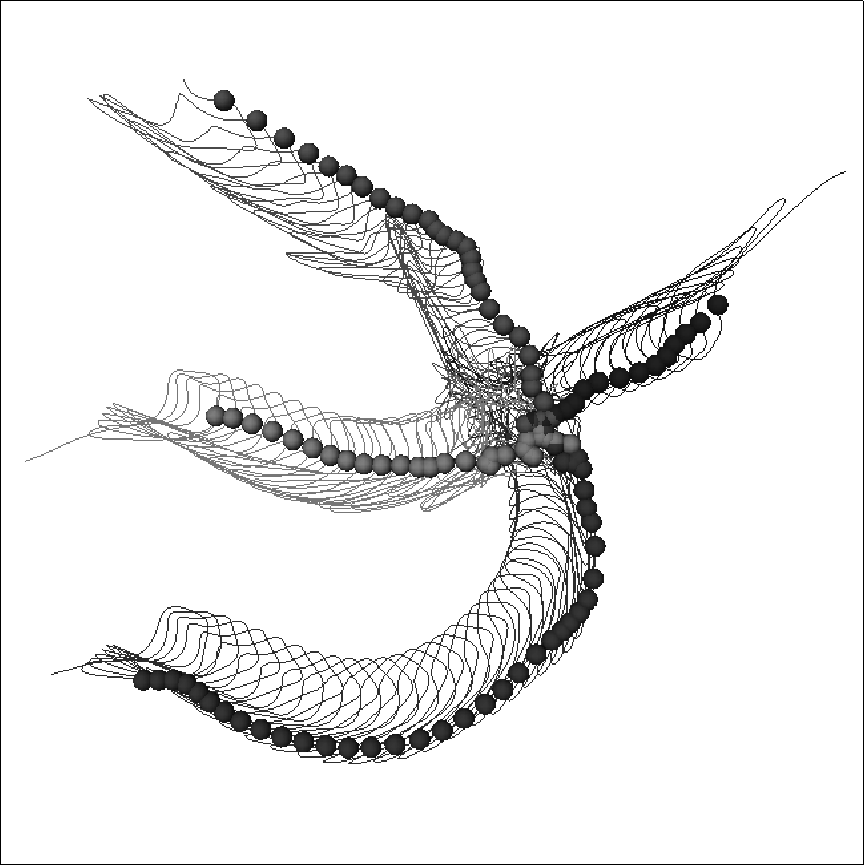
Small amplitude, spatially uniform repetitive stimulation can be used to produce directed movement of a rigidly rotating spiral wave, if the period of stimulation is equal to the period of the spiral wave rotation (resonant drift). If the stimulation period is close but not equal to the rotation period of the spiral a circular drift is obtained [29, 30]. If the stimulation period is fixed, this drift is strongly influenced by medium inhomogeneities [31]. Such a drift has been observed in reaction-diffusion model of rabbit atrium based on Earm-Hilgemann-Noble kinetics [32]. In the OGPV model, even in the absence of inhomogeneities, the instantaneous frequency of the spiral is always changing, because of the meander and the slow change of the spiral wave period due to aging and so a pure resonant drift is not observed at any constant frequency. A typical trajectory, produced by constant frequency perturbation of a meandering OGPV spiral, is shown in Fig. 8.

Figure 8:
A ![]() piece of the tip trajectory of a spiral wave in the 2D OGPV
model under uniform external forcing F(x,y,t)=F(t) of pulses of
amplitude of
piece of the tip trajectory of a spiral wave in the 2D OGPV
model under uniform external forcing F(x,y,t)=F(t) of pulses of
amplitude of ![]() (
( ![]() ) and duration of
) and duration of
![]() , with period
, with period ![]() . The balls show the tip positions at
the beginning of each stimulus. Newer pieces are darker and older are
lighter. This is defined by three processes
stimulation+meander+aging.
. The balls show the tip positions at
the beginning of each stimulus. Newer pieces are darker and older are
lighter. This is defined by three processes
stimulation+meander+aging.
The resultant motion is a nonlinear interaction between the pattern of
meander and the motion produced by the perturbations. The directed
motion of resonant drift is much more robust if instead of choosing a
fixed frequency, some kind of feedback is used to synchronise the
stimulation with the spiral wave rotation [33, 30]. Such
feedback control can provide the stable resonant drift in the OGPV
model [19]. Figure 9 shows four tip trajectories
produced by repetitive stimulation applied at four different fixed
delays after the wavefront reached the bottom left corner. The delay
determines the initial direction of drift. A repetitive perturbation of
15% the amplitude of the single shock defibrillation threshold
produces a directed motion with a velocity of about ![]() .
.

Figure 9:
Tips trajectories of resonantly drifting spirals, with feedback via\
registered electrode in the bottom left hand corner of the medium and
delays 0, 25, 50 and ![]() ; average period of rotation is within 100
to
; average period of rotation is within 100
to ![]() , square size
, square size ![]() . The uniform
stimulation F(x,y,t)=F(t) was by pulses
. The uniform
stimulation F(x,y,t)=F(t) was by pulses
![]() long
long ![]() (
( ![]() ) strong. The balls show the tip positions
at the beginning of each stimulus. The visible fractures in the
trajectories correspond to different phase locks between stimulation
and meander.
) strong. The balls show the tip positions
at the beginning of each stimulus. The visible fractures in the
trajectories correspond to different phase locks between stimulation
and meander.